
When you're staring at a dead phone or a misbehaving gadget, it’s easy to feel frustrated. The problem could be anything, and you might be tempted to start guessing or spending money on new parts. Before you do, there’s one diagnostic skill that will save you time, money, and headaches: learning how to check continuity with a multimeter. This quick test is the foundation of electronic repair, telling you if a circuit has a clean, unbroken electrical path, and it's a core technique our technicians use for iPhone repairs in Brisbane every day.
Why Continuity Testing Is Your First Diagnostic Step
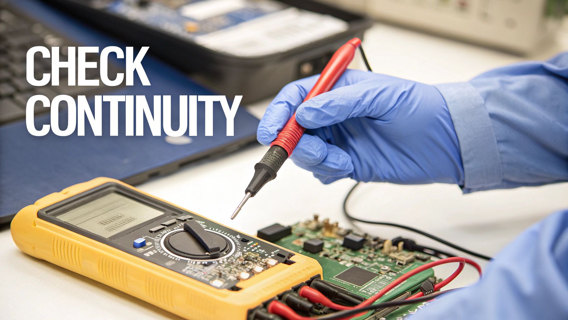
alt="A technician checks a circuit board for continuity using multimeter probes."
Think of the circuits inside your phone like a complex network of highways. For electricity to get from point A to B, all the roads and bridges need to be intact. A continuity test is how you check for roadblocks—like a broken wire or a fried component.
Often, a device fails because of a simple break in a circuit. It could be a tiny crack in a solder joint, a torn flex cable, or a faulty switch. Instead of swapping out an entire motherboard, a continuity test lets you zoom in on the exact point of failure. It's the same precise method our technicians use every day to diagnose issues accurately.
The Power of a Simple Beep
The real beauty of the continuity test is its simplicity. Your multimeter sends a tiny bit of current through one probe and listens for it at the other. If the path is complete, you get an unmistakable, audible beep.
That single sound gives you a clear answer:
- Beep: Yes, you have a clean, unbroken connection.
- Silence: Nope, the path is broken. You've found a fault.
This instant feedback is priceless. For instance, if a phone's power button isn't responding, you can test the flex cable connecting it to the logic board. A beep tells you the cable is good, so the problem must be somewhere else. No beep? You've just found your culprit. The same logic applies when figuring out why your USB ports are not working, letting you isolate the problem in minutes.
A quick rundown of what your multimeter is telling you can make diagnostics even faster.
Continuity Test Results at a Glance
This table breaks down the three main outcomes you'll encounter and what they mean for your repair.
| Multimeter Reading | What It Means | Common Example in Phone Repair |
|---|---|---|
| Audible Beep & ~0Ω | Good Continuity: A clear, complete path exists. | A healthy fuse or an intact trace on the logic board. |
| No Beep & "OL" | Open Circuit: The path is broken. No connection. | A torn flex cable or a blown fuse. |
| No Beep & High Ohms | High Resistance: There's a connection, but it's poor or a component is in the way. | A corroded contact point or measuring across a resistor. |
Getting comfortable with these readings is the key to moving from guessing to knowing.
Beyond Phone Repairs
This skill isn't just for mobile devices. It's a fundamental technique for anyone tinkering with electronics, from DIY hobbyists to professional electricians. For example, when installing a WiFi light switch, checking for continuity is a critical safety and functional step.
By mastering this one test, you stop wasting money on parts you don’t need and start fixing things with confidence. It’s the ultimate diagnostic shortcut, empowering you to find the root cause of almost any electrical problem.
Setting Up a Safe and Effective Workspace
alt="A safe and organised workspace is essential for multimeter testing."
Before your probes even get near a circuit board, setting up a safe and organised workspace is non-negotiable. Jumping straight into a repair without proper prep is a recipe for disaster, risking fried components or even personal injury. This isn't just about clearing a bit of space; it's about having the right gear and the right mindset from the get-go.
Your main tool, obviously, is a trustworthy multimeter. But for the delicate work inside modern electronics like an iPhone or a Samsung, you'll need more than just any old probes. Standard ones are often too blunt. You’ll absolutely need probes with sharp, fine tips to make solid contact with those tiny solder points and pins.
Your Essential Toolkit
Beyond the multimeter itself, a few other items will make your life a lot easier and your diagnostics much safer. Think of this as your pre-flight checklist before starting any continuity test.
- Antistatic Wrist Strap: This simple strap connects you to a ground point, stopping static electricity from your body from zapping sensitive microchips. Electrostatic discharge (ESD) is a silent killer of electronics.
- Insulated Tweezers: You'll be glad you have these for handling tiny components and wires without causing accidental shorts. Regular metal tweezers can easily bridge two connections and create a whole new problem for you to solve.
- A Good Light Source: A bright, adjustable lamp is crucial. You can't test what you can't see, and modern logic boards are packed with minuscule traces and components.
You’ll also need the right tools to actually open the device. Using the correct drivers prevents the headache of stripped screws and frustration. It pays to learn about the different screw drive types so you're ready for whatever a device throws at you.
The Golden Rule: Power Down Completely
This is the most critical step of all, and there are no shortcuts. Before you even think about checking continuity, you must completely power down the device. And that means more than just hitting the off button.
Safety First: Always disconnect the battery from the logic board before any test probes make contact. Testing a live circuit can permanently damage the component, your multimeter, and even cause a dangerous short circuit.
This isn't a suggestion; it's a fundamental rule of electronics repair that will save you from costly mistakes. With your workspace prepped and all safety measures in place, you're finally ready to get your multimeter configured for the test.
Alright, let's get your multimeter set up to hunt for continuity. It's a simple process, but getting these first few steps right is the difference between a quick diagnosis and a wild goose chase. Think of it like tuning a guitar—a moment of preparation makes sure every note (or reading) is spot on.
First up, the probes. Your multimeter has dedicated ports, and it's vital to plug them in correctly. The black lead always goes into the port labelled "COM". COM stands for common, which is essentially your ground point. The red lead gets plugged into the port marked VΩmA, the all-in-one port for measuring voltage (V), resistance (Ω), and milliamps (mA).
Finding the Right Setting on the Dial
With the probes securely in place, it’s time to turn the rotary dial to the right function. You're looking for the continuity setting. On just about any modern digital multimeter, this mode is marked with a symbol that looks like a sound wave (like a dot with radiating curved lines) or sometimes a diode (a triangle pointing at a line).
When you turn the dial to this symbol, you’re telling the multimeter to send a tiny electrical current out through one probe and listen for it with the other. If it detects that current, it knows the path is complete and will let out a beep.
Pro Tip: Before you even touch the device you're testing, always check your meter first. Just touch the metal tips of the red and black probes together. You should hear an instant, loud beep and see a reading on the screen very close to zero. It’s a simple habit that confirms your multimeter, its battery, and the probes are all working as they should.
Trust me, this little self-test has saved countless technicians from the headache of chasing phantom problems that were actually caused by a dead battery or a dodgy probe. No beep? Check your connections and the battery before you do anything else.
Understanding the Beep and Ohms
That audible beep is the classic sign of good continuity, but the number on the screen tells you the full story. That number represents the resistance in the circuit, measured in ohms (Ω). A clean, unbroken connection has virtually no resistance, which is why a solid continuity test will show a reading that's almost 0Ω.
A great real-world example of this comes from a freelance tech in Brisbane working on an Apple Watch. He grabbed his Fixo DIY kit, powered off the device (a critical safety step!), and set his multimeter to the sound wave icon to test a suspect flex cable. He got a clear beep and a reading of 0.5 ohms. That one simple test confirmed the cable was perfect, saving him from forking out AU$150 for a screen replacement he didn't need. You can learn more about these essential safety practices from the pros. (HVAC Shop's 2025 guide)
The link between the beep and a low ohm reading is what it's all about. It’s your confirmation that electricity has a clear, unimpeded path to flow—exactly what you want to find in a healthy wire, fuse, or circuit trace.
How to Interpret Your Multimeter's Feedback
With your probes in place, it’s time for the moment of truth. This is where the theory of continuity testing turns into a real, actionable diagnosis. Your multimeter gives you instant feedback, and learning to speak its language is the key to any successful repair.
You'll usually get one of three main outcomes, and each one tells a very different story about the circuit you're probing.
The Clear Yes: A Beep and Near-Zero Ohms
The most satisfying result is that loud, steady beep you hear the second your probes make contact. At the same time, glance at your multimeter’s screen—you should see a resistance reading that's incredibly close to zero, something like 0.1Ω or 0.2Ω.
This combination is a definite "yes." It confirms you've got a perfect, clean, and unbroken electrical highway between your two test points. It means there's excellent continuity, with practically no resistance to get in the way of electricity flowing. If you were testing a fuse and got this result, for instance, you'd know instantly that the fuse is good and the fault is somewhere else.
The Definitive No: An Open Loop
The complete opposite is dead silence—no beep at all. When you look at the screen, your multimeter will probably show "OL" (which stands for Open Loop) or sometimes just a "1" sitting on the far left of the display.
This is a clear "no." It tells you the path is completely broken. There is zero electrical connection between your two points. This is exactly what you'd expect to see if you were testing a blown fuse, a ripped flex cable, or a severed trace on a logic board. Congratulations, you've found the break.
When our technicians are working on an iPhone that won’t charge, for example, they'll often test the pins on the charging port flex cable. An "OL" reading on a critical power line instantly confirms that the cable is faulty and needs replacing. If that sounds like your issue, you can learn more about how to fix an iPhone charger port in our detailed guide.
The Tricky Middle Ground: High Resistance
This is where things get interesting, as it’s the most subtle and often the most confusing result you can get. In this situation, you won't hear a beep, but instead of "OL," your multimeter will display a specific resistance value that could be anything from a few dozen ohms to thousands.
This reading means a path for electricity does exist, but it's a terrible one. The connection is weak, corroded, or partially damaged, creating high resistance that's essentially choking the electrical flow. These are the kinds of faults that cause those frustrating intermittent problems, like a button that only works when it feels like it or a phone that randomly reboots.
A real-world example might be a Google Pixel with an unresponsive volume button. Probing the connection on the motherboard might show a reading of 500Ω but no beep. While it's not a total break, that much resistance is more than enough to stop the button's signal from registering correctly, pointing straight to something like a corroded contact pad that just needs a good clean.
This simple decision tree helps visualise the basic setup steps that lead to these diagnostic results.
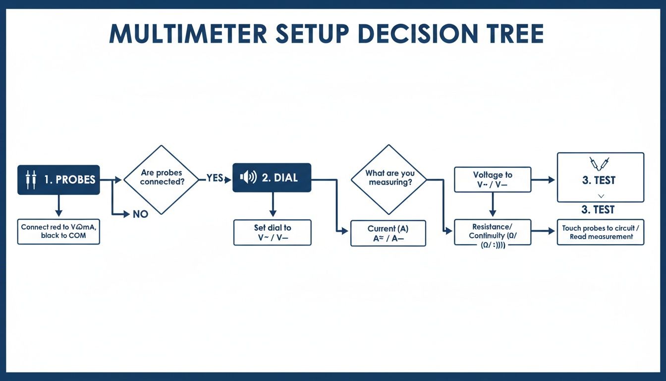
alt="Flowchart showing the steps to set up a multimeter for a continuity test."
As the flowchart shows, it’s a straightforward process: connect your probes, turn the dial to the right setting, and touch the points to get your reading.
Being able to spot these subtle high-resistance faults is what separates a good repair from a great one. For example, a professional technician can de-energise a Motorola device, set their meter to continuity, and quickly confirm that the main ground traces on the PCB show a solid 0 ohms. This is a vital check, as undetected open circuits were responsible for 19% of all electronic failures in 2023.
Avoiding Common Mistakes and Pitfalls
Even seasoned technicians can get tricked by misleading continuity readings. On the surface, it seems simple enough, but a few common slip-ups can send you down a diagnostic rabbit hole, wasting time and money on parts you never needed. Really mastering how to check continuity with a multimeter means knowing what can go wrong and how to spot it.
One of the most frequent errors I see is misinterpreting a reading from a parallel circuit. Imagine you're testing a path from point A to point B. If another component is connected alongside it, it creates a 'backdoor' for the current. Your multimeter will happily find this alternate route and beep, giving you a false positive for the specific path you thought you were testing.
The only way to be certain is to isolate the component. This usually means desoldering one end of it from the board to ensure your multimeter is only reading that specific part. It feels like an extra step, but it’s the only way to guarantee an accurate diagnosis.
Navigating Sneaky Components
Some components are just plain tricky by nature and can easily fool a continuity test if you're not paying attention. Diodes and transistors, for instance, are the electronic equivalent of a one-way street—they’re designed to allow current to flow in only one direction.
If you test a diode in the 'forward' direction, you'll likely get a reading. But test it in reverse, and your meter will show an open loop ("OL"). The component isn't broken; it's just doing its job. When you come across a diode, it’s always best to switch your multimeter over to its dedicated diode test mode. This will give you a much more useful reading of its forward voltage drop.
A classic scenario we see in the workshop is testing a flex cable for an intermittent fault. A standard continuity test might show everything is fine, but the fault only rears its head when the phone is assembled and the cable is bent into position. The pro-level trick here is to gently flex and wiggle the cable while your probes are connected. If that beep cuts out for even a second, you've just found your culprit.
The Problem of Phantom Readings
Another classic pitfall is failing to get a clean, solid connection with your probes. The tiny test points on a modern logic board can be covered in a thin, invisible layer of conformal coating or oxidation. If your probes don't make good metal-to-metal contact, you'll get an "OL" reading even on a perfectly good circuit.
Always use sharp-tipped probes and apply firm, steady pressure. If you're still not getting a reading where you expect one, a bit of isopropyl alcohol on a cotton swab can help clean the contact point. This simple clean-up can be the difference between a correct diagnosis and ordering a part you don't actually need.
We rely on these advanced diagnostic techniques every day for complex iPhone repairs in Brisbane. They are absolutely crucial for avoiding misdiagnosis and getting the job done right the first time.
Troubleshooting Your Continuity Test Results
When your test results just don't seem to add up, this quick reference table can help you figure out what might really be going on.
| Symptom | Potential Cause | How to Verify and Fix |
|---|---|---|
| Beep on a known bad circuit | A parallel component is creating an alternate path for the current. | Isolate the component by desoldering one end before retesting. |
| "OL" on a diode or transistor | Probes are oriented against the component's one-way current flow. | Switch to diode test mode and check the component in both directions. |
| No beep, but the fault is intermittent | The break in the circuit only appears under physical stress. | Gently flex the cable or tap the board while testing to see if the reading changes. |
| "OL" on a known good connection | Poor probe contact due to dirt, oxidation, or conformal coating. | Clean the test points with isopropyl alcohol and use sharp probes with firm pressure. |
Hopefully, this helps you sidestep some of the most common issues and read your multimeter with more confidence.
Your Continuity Testing Questions Answered
Even with a solid grasp of the process, a few common questions always seem to pop up right when you're in the middle of a repair. We’ve pulled together the most frequent ones our technicians hear to give you clear, practical answers that will help you test with confidence.
What Is the Difference Between Continuity and Resistance Modes?
Think of your multimeter’s modes as two different tools for basically the same job. The continuity test is your quick-and-dirty check. It's a simple pass/fail assessment that gives you a 'yes' (beep) or 'no' (silence) on whether an electrical path is complete. It’s perfect for rapidly finding a broken wire or just confirming a connection is solid.
Resistance mode, on the other hand, is all about precision. Instead of just a 'yes' or 'no', it tells you exactly how much that path is resisting the flow of electricity, giving you a specific reading in Ohms (Ω). You’d switch over to resistance mode when you need to measure a specific component, like a resistor, or to investigate a partial fault where you have a connection, but it's weak or dodgy.
For most initial diagnostics, you'll always start with continuity. It's faster.
Can I Test Continuity with the Battery Connected?
Absolutely not. This is probably the most critical safety rule in all of electronics repair, and it’s one that should never, ever be broken. Trying to check continuity on a live circuit—one with the battery connected or power still flowing—is the fastest way to cause catastrophic damage.
Critical Warning: Sending current from your multimeter into a powered-on logic board can instantly fry sensitive components, short out the board, damage your multimeter's internal fuse, or even cause the battery to spark. Always power down the device and physically disconnect the battery before your probes touch anything. No exceptions.
Why Do I See a Low Number But Get No Beep?
This is a fantastic question because it gets into a subtle but really important detail. Most digital multimeters have a preset resistance threshold for the audible beep, often somewhere under 50 Ohms. If the resistance of the path you're testing is above that cutoff, the beeper won't sound, even though a connection technically exists.
When you see a low reading without a beep, like 100Ω, it’s signalling a high-resistance fault. This often points to things like a corroded contact point, a partially failed solder joint, or a damaged wire that’s just barely hanging on. It’s an electrical bottleneck that needs a much closer look, as it's a common cause of those frustrating, intermittent issues.
I Found a Broken Circuit. What Now?
Congratulations! Pinpointing the exact point of failure is the most important part of any successful repair. Once you've used your multimeter to confirm a broken circuit or a faulty component, the next step is to source a high-quality replacement part and perform a reliable repair.
If you've found the problem but don't feel comfortable completing the fix yourself, it's always best to hand it over to a professional. A botched repair can easily create more problems than it solves, turning a simple fix into a major headache.
For a trustworthy fix for your device, the team at Screen Fixed Brisbane has the expertise and quality parts to get it working perfectly again. Book your repair with us today.
Disclaimer: iPhone, Samsung, Google Pixel, Motorola, and Apple Watch are trademarks of their respective owners. Screen Fixed is an independent repair service and is not affiliated with these brands.
meta title: How to Check Continuity with a Multimeter | Step-by-Step Guide
meta description: Learn how to check continuity with a multimeter to diagnose and fix electronics. Our simple guide covers setup, reading results, and common mistakes.