
meta title: How to Test Continuity with a Multimeter | Screen Fixed Guide
meta description: Learn how to test continuity with a multimeter with our expert guide. Follow our step-by-step instructions for DIY electronics repair in Australia.
Is your favourite gadget suddenly dead? Before you panic, the problem might be a simple break in an electrical path—something a quick continuity test can find in seconds. Learning how to test continuity with a multimeter is one of the most fundamental skills for diagnosing electronics. At its heart, it's pretty simple: you'll set your multimeter to continuity mode, touch the probes to two points on a circuit, and listen for that satisfying beep that tells you the electrical path is complete. This guide will walk you through exactly how to do it safely and accurately.
Why Continuity Testing Is Your First Step in DIY Electronics Repair
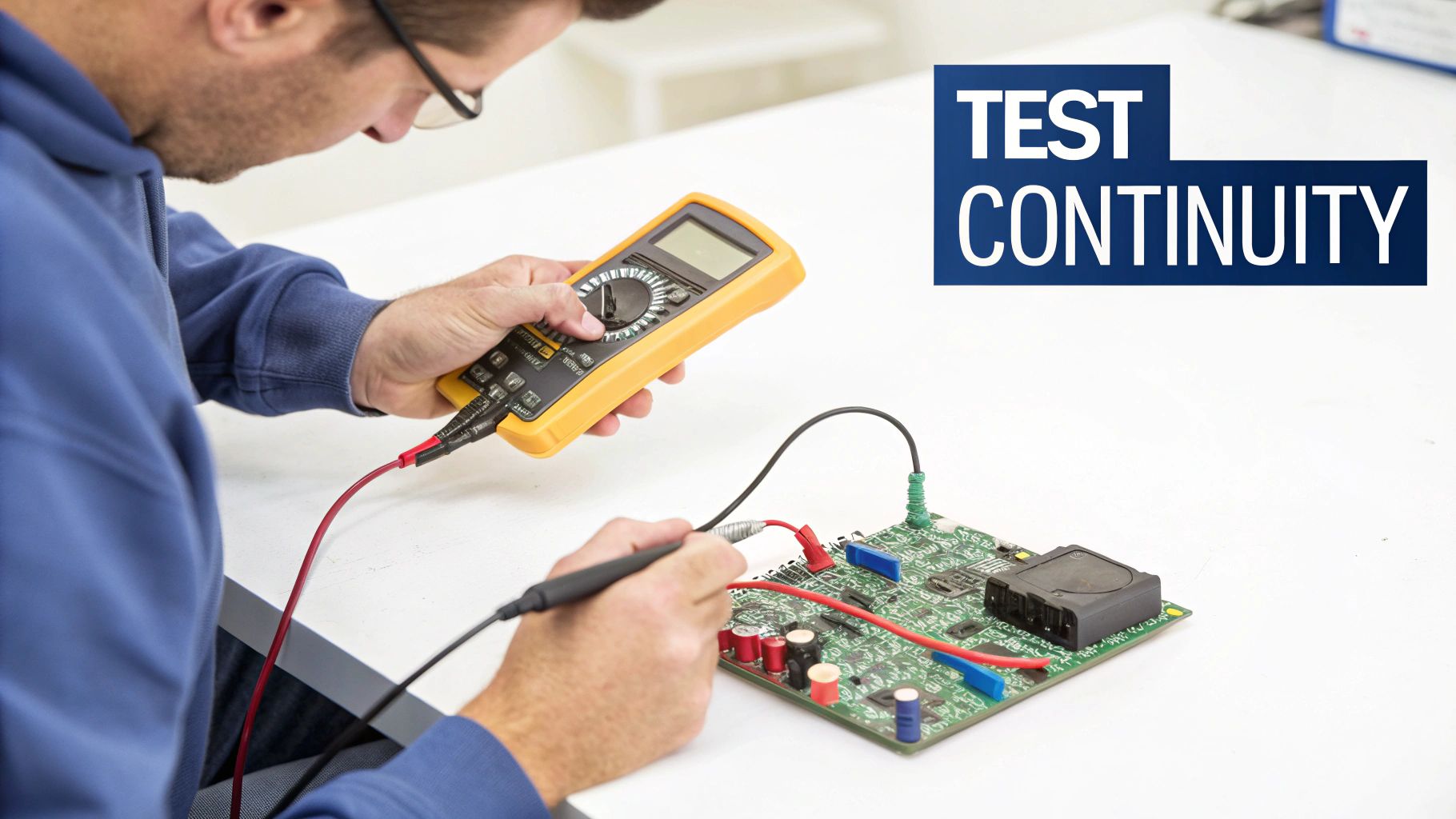
alt text: A digital multimeter set to continuity mode, held over a circuit board ready for testing.
Ever had that moment of frustration when a favourite gadget just stops working? You're left wondering if a fuse has blown or maybe a tiny switch has given up the ghost. The culprit is often just a simple break somewhere in an electrical path, but finding that break can feel like searching for a needle in a haystack. This is exactly where continuity testing comes in—it’s your go-to diagnostic tool.
Understanding the Basics of Continuity
At its core, continuity is just the presence of a complete, unbroken path for electricity to flow. Picture it as a highway for electrical current. If there’s a collapsed bridge (like a broken wire) or a closed gate (a faulty switch), the traffic comes to a dead stop. A continuity test is simply how you check if that highway is clear from point A to point B.
This straightforward check helps you answer critical questions in seconds:
- Is this wire actually intact, or is there a hidden break?
- Is this switch really opening and closing the circuit like it should?
- Has this fuse blown, creating an open circuit?
By ruling these simple things in or out right away, you can often pinpoint the exact source of a problem without diving into hours of complex troubleshooting. It's a foundational practice for electrical fault-finding right here in Australia. In fact, over 85% of licensed electricians lean on their multimeters for continuity tests as a routine part of their diagnostics, a method that’s backed by Australian Standards for safe electrical work.
Safety First: Before You Even Touch a Probe
Before your multimeter probes get anywhere near a circuit, you need to remember the golden rule of electronics repair: always make sure the device is completely powered down. This isn’t just about unplugging it from the wall. You also need to remove any batteries and give it a few moments for any stored energy in components like capacitors to safely dissipate.
A live circuit can do more than just damage your multimeter; it poses a serious risk of electric shock. Safety isn't a suggestion—it's a non-negotiable step before every single test.
Getting comfortable with tools like the multimeter is a huge first step on any repair journey. For those looking to expand their hands-on know-how, it's also worth checking out other practical skills for DIY enthusiasts.
Getting Your Multimeter Ready for the Test
Before you can start poking around inside a device, you need to get your multimeter set up properly. It’s a quick process, but getting it right from the start is what separates a fast, accurate diagnosis from a frustrating goose chase. A few simple mistakes here can throw off your entire test.
First things first, let's plug in the probes. Your multimeter has a few ports, but for continuity testing, you only care about two. The black probe always goes into the port labelled “COM”—that stands for common, which is your ground. The red probe plugs into the port that handles voltage (V), resistance (Ω), and milliamps (mA), which you'll usually see marked as VΩmA. It's a fundamental step, but getting it backwards is a common beginner slip-up.
Dialling in the Right Mode
With the probes securely in place, it's time to turn the rotary dial to the right setting. You’re looking for continuity mode. On most meters, this is indicated by a symbol that looks like a soundwave or a series of expanding arcs. It’s often on the same setting as the diode test symbol.
When you select this mode, you're telling the multimeter to do two things:
- Send a very small electrical current out of one probe.
- Listen for that current to return through the other probe.
If the current finds its way back, you have a complete, unbroken path—you have continuity. The multimeter signals this by letting out an audible beep, which is what makes this mode so incredibly handy for quick-fire troubleshooting.
The One Pre-Test Check You Can’t Skip
Now for the final, crucial step that every seasoned tech does without even thinking: touch the tips of your two probes together. You should hear a sharp, immediate beep from your meter.
This simple action is a sanity check. It instantly confirms your probes are plugged in right, the continuity setting is working, and the meter's battery isn't dead. If you don't hear that beep, something is wrong with your setup.
Think of it as calibrating yourself to the tool. That beep becomes your baseline for a 'good' connection. It gives you the confidence that when you start testing components, the results you get are trustworthy. A solid smartphone repair tool kit usually includes a decent multimeter, so it's easy to make this professional check a habit. Once you hear that beep, you’re officially ready to start probing and find out what’s really going on.
How to Perform a Continuity Test on Common Components
Alright, with your multimeter set up and ready to go, it's time for the real detective work. This is where we put theory into practice and start probing the components you'll come across most often. Before we dive in, let's repeat the golden rule: always make sure the device is completely powered down and the battery is disconnected. Seriously, safety first.
Now, let's get our hands dirty with a few common scenarios.
Checking a Simple Wire or Cable
The most fundamental continuity test you'll ever do is on a plain old wire. This could be a charger cable, a headphone wire, or a tiny trace connecting two points on a circuit board. You’re simply checking for an unbroken electrical path from one end to the other.
It's as easy as it sounds. Just place one probe firmly on one end of the wire and the other probe on the opposite end. If the wire is good, your multimeter should give an instant, satisfying beep. If you get silence, you’ve just found a break somewhere in the line. This basic skill is incredibly useful for everyday problems, like diagnosing a charger that is not working, where a broken cable is a frequent culprit.
Testing a Switch for Correct Operation
Switches are a little different because their job is to interrupt a circuit. That means you need to test them in both their 'on' and 'off' states to know if they're working properly.
Start by finding the input and output terminals of the switch. Flick it to the 'on' (closed) position and touch a probe to each terminal. You should hear a clear, continuous beep, which tells you the path is complete, just like it's supposed to be.
Now, keep your probes in place and flick the switch to the 'off' (open) position. The beeping should stop dead. If it beeps in both positions, your switch is stuck closed. If it never beeps at all, it's stuck open. It’s a quick, two-step check that instantly tells you the health of the switch.
To help you remember the multimeter setup, here’s a quick visual recap of the steps we went over earlier.

alt text: Infographic showing the 3 steps to set up a multimeter for a continuity test: plug in probes, turn dial to continuity mode, touch probes to test.
This simple sequence is your go-to every time you pick up your meter for a test.
How to Quickly Check a Fuse
Fuses are the unsung heroes of electronics, designed to be the weak link that breaks a circuit if too much current flows through. A continuity test is the absolute fastest way to tell if a fuse has done its job and blown.
Think of a good fuse as just a tiny wire in a glass or ceramic tube. Because it's an unbroken wire, it should always have continuity.
Just touch one probe to each of the metal caps on the ends of the fuse. Hear a beep? The fuse is good. Hear nothing but silence? The fuse has blown, creating an open circuit, and needs to be replaced. This test takes literally five seconds and can save you hours of pointless troubleshooting.
It’s one of the first things I check when I see a device with dead USB ports not working, as a tiny blown fuse on the logic board is often the culprit. This kind of practical know-how is what we rely on every day, whether you're at our Screen Fixed Brisbane shop or working on your own bench at home.
What Your Multimeter's Readings Really Mean
Getting a beep or a number on your multimeter's screen is one thing, but knowing what that feedback actually means is where the real skill comes in. This is what separates someone just poking at a board from a technician who can confidently diagnose a problem.
Let's start with the most obvious signal: the beep. A clear, steady tone from your multimeter is the simplest, most direct confirmation you can get. It's telling you there's a solid, unbroken electrical path between your two probes. Think of it like a clear highway for electricity to travel down—you've got good continuity.
The Sound of Silence
But what if you place your probes and hear… nothing? That silence is just as telling as a loud beep. It screams "open circuit", which means there's a break somewhere along the path. This is exactly what you'd expect to find on a blown fuse, a snapped trace on a circuit board, or a switch that’s failed in the 'off' position.
An open circuit is your cue to start hunting for the physical break. The silence points you straight toward the root of the problem.
Diving Into the Numbers
While the beep is fantastic for a quick 'yes' or 'no', the numbers on the display tell a more nuanced story. With good continuity, you’ll see a resistance value that's very close to zero ohms (Ω). A reading between 0.0 and 0.5 Ω is a great sign for a healthy wire, trace, or fuse, confirming an almost perfect path for current.
On the flip side, when you have an open circuit, the screen will usually show 'OL'. This stands for 'Over Limit' or 'Open Loop'. It means the resistance between your probes is so high that the meter can't measure it—for all practical purposes, it's infinite. Seeing 'OL' is the numerical equivalent of silence; it confirms a definite break in the circuit.
Key Takeaway: A beep and a near-zero ohm reading tell you the same thing: you have good continuity. Silence and an 'OL' reading also mean the same thing: there’s no continuity, which points to an open circuit.
Getting a handle on these basic readouts is fundamental to learning how to test continuity with a multimeter. It’s the language your tool speaks, and you need to be fluent to understand what's happening inside the device.
To make it even clearer, I've put together a quick reference table. It breaks down what you'll see on the meter and what your next move should be.
Continuity Test Results and What They Mean
| Multimeter Reading | What It Indicates | Common Cause | Your Next Step |
|---|---|---|---|
| Continuous Beep | Good Continuity | An intact wire, a good fuse, or a closed switch. | The component is working correctly. Move on to test the next part of the circuit. |
| Near-Zero Ohms (0-1Ω) | Good Continuity | A solid, low-resistance electrical path. | Confirm the part is healthy and continue troubleshooting elsewhere. |
| Silence (No Beep) | No Continuity / Open Circuit | A broken wire, a blown fuse, or an open switch. | You've found the faulty component. Prepare to repair or replace it. |
| "OL" (Over Limit) | No Continuity / Open Circuit | Infinite resistance between the probes. | This confirms a break. Isolate the faulty part for replacement. |
Once you're comfortable with these interpretations, you'll be able to quickly diagnose a dodgy charge port flex, a dead power button, or any other break in a circuit. It’s a core skill that moves you one big step closer to wrapping up a successful repair.
Common Mistakes and Pro Tips for Accurate Results

alt text: A technician's hands carefully using multimeter probes on a small electronic circuit board for a phone repair.
Knowing how to perform a continuity test is one thing, but getting consistently reliable results is a different game entirely. It's easy to get led astray by a few common traps. I've pulled these tips straight from what we see every day in our iPhone repairs Brisbane workshop to help you avoid the frustration of a misdiagnosis.
The absolute number one mistake? Testing a live circuit. I know we've said it before, but it’s so critical it’s worth repeating: never probe a device that’s still powered on or has a battery connected. It's a surefire way to fry your multimeter, destroy the delicate components you’re trying to fix, and it puts you at serious risk of a nasty shock.
Another classic error is not getting a good, solid contact with your probes. The solder joints and test points on modern boards are tiny, and they can easily be covered in a thin layer of flux residue or even oxidation. A weak or flimsy connection will give you a false 'open circuit' reading, sending you down a diagnostic rabbit hole for no reason.
Pro Tip: Don't be shy—press your probe tips firmly onto the test points. If a connection feels a bit dodgy, you can gently scrape the point with your probe to break through any surface gunk. For really fine work, a good set of sharp, needle-point probes is worth its weight in gold.
Dodging Ghost Readings from Parallel Components
This is a sneakier issue that catches a lot of people out. When you test a component while it's still soldered to the board, you’re not just measuring that single part. You're actually measuring everything else that's connected to it in parallel.
Let's say you're checking a resistor you think might be blown. If there's another component on a parallel path, the current from your multimeter will just take the path of least resistance and flow right around the faulty resistor. Your meter will beep, you'll see a good continuity reading, and you'll be tricked into thinking the bad component is perfectly fine.
- How to avoid this: The only way to be 100% sure is to isolate the component. You can do this by desoldering and lifting at least one leg of the part off the board. This completely removes it from the rest of the circuit, guaranteeing your reading is accurate.
Dealing with Tricky Circuits and Coatings
Things can get even more complex, especially with liquid damage. Corrosion loves to hide under components where you can't see it, creating breaks in continuity that come and go. Our guide on how to fix a water-damaged phone dives deeper into how these hidden faults can crop up.
Lastly, watch out for conformal coatings. A lot of modern electronics have a thin, transparent, non-conductive layer sprayed over the entire board to protect against moisture. You have to physically and carefully pierce this coating with your probe tip to make electrical contact with the test pad underneath. If you don't, you'll just get a false 'OL' reading every single time. Keep these nuances in mind, and you'll be testing with far more confidence and accuracy.
Frequently Asked Questions
Even after you get the hang of it, continuity testing can throw you a curveball now and then. Getting reliable results means understanding the little quirks and limitations of your multimeter. Let's tackle some of the most common head-scratchers that come up during electronics repair.
Can I test a component while it's still on the board?
You can, but it's not recommended if you need an accurate result. When a component is still soldered in place, you're not just testing that single part; you're testing everything else connected to it in parallel. The current from your meter will find the easiest path, which can give you a false positive reading, making you think a faulty part is fine. To be 100% sure, you need to isolate the component by desoldering at least one of its legs from the circuit board.
What's the real difference between continuity and resistance modes?
Think of continuity mode as your quick "yes/no" check. It's designed for one simple purpose: to tell you if a connection exists, usually with a loud beep. Resistance mode (the Ohm 'Ω' symbol) is for when you need specifics. It gives you the exact numerical value of how much opposition that path has to current flow. Use continuity for checking wires and fuses, and switch to resistance mode when you need to measure the actual value of a component like a resistor.
Help! My multimeter won't beep!
If you touch your probes together and get silence, don't panic. First, double-check that the dial is on the continuity setting and the probes are plugged into the correct jacks (black in COM, red in VΩmA). The most common culprit is a weak battery, as the beeper needs a fair bit of power. If a new battery doesn't fix it, you may have a blown internal fuse in the meter or a broken probe lead.
What does that 'OL' on the screen mean?
When your multimeter displays 'OL', it stands for 'Over Limit' or 'Open Loop'. It means the resistance between the two probes is so high that it can't be measured—it’s effectively infinite. In a continuity test, 'OL' is the opposite of a beep. It's a clear confirmation that there is no electrical path between the two points you're testing, which is what you'd expect from a broken wire or blown fuse.
Feeling more confident but still stuck on a repair? Sometimes, you just need a professional touch. The team at Screen Fixed Brisbane has the gear and the expertise to track down even the most stubborn faults. Book your repair with Screen Fixed Brisbane today, and we'll get your device back in action.
Disclaimer: All third-party trademarks (including logos and icons) referenced by Screen Fixed remain the property of their respective owners. Unless specifically identified as such, Screen Fixed’s use of third-party trademarks does not indicate any relationship, sponsorship, or endorsement between Screen Fixed and the owners of these trademarks.